
- #HOW TO EDIT THE SOLDER MASK IN SPRINT LAYOUT SOFTWARE#
- #HOW TO EDIT THE SOLDER MASK IN SPRINT LAYOUT PROFESSIONAL#
- #HOW TO EDIT THE SOLDER MASK IN SPRINT LAYOUT DOWNLOAD#
- #HOW TO EDIT THE SOLDER MASK IN SPRINT LAYOUT WINDOWS#
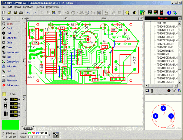
The library is displayed in a well sorted treeview, so you don’t have to spend much time for searching a component. The component-library is already filled with many common used components, either in SMD or in conventional through-hole-technology. Additional functions like copy, move, rotate, mirror, etc. For example if you adjust the width of a track, you will see the result immediately on your layout. You can edit existing layout-elements very easy. The active grid-capture lets you easily place your elements exactly. are always visible at a glance, and can be edited every time. All parameter like track-width, pad-size, etc.

Just select the corresponding mode and place your elements.

Sprint-Layout is equipped with tools to draw pads, tracks, copper areas, labels and so on.
#HOW TO EDIT THE SOLDER MASK IN SPRINT LAYOUT DOWNLOAD#
With the free viewer for Sprint-Layout-files it is possible for everybody to view or print your layouts.Īre you getting curious? Here you can download the free demoversion of Sprint-Layout 6.0. You can load all older layout-files and edit them with the new version. Of course the new version 6.0 is fully compatible to all older versions of Sprint-Layout. As always, we take very much care of an user-friendly operation.
#HOW TO EDIT THE SOLDER MASK IN SPRINT LAYOUT SOFTWARE#
The new version 6.0 includes many new features and improvements, which makes the software more comfortable. If you own a CNC milling-machine, Sprint-Layout is also able to create HPGL files for isolation-milling. If required, you can export your layout to the GERBER and EXCELLON format which are supported by almost every PCB-manufacturer.
#HOW TO EDIT THE SOLDER MASK IN SPRINT LAYOUT PROFESSIONAL#
If you want to produce professional boards, there are many PCB-manufacturer, which accept Sprint-Layout files. Of course, there is an extensive library with all common components included.įor manufacturing your PCB’s by hand, there is an excellent printout-procedure with many options available. Sprint-Layout offers all needed and many helpful functions to design your own layouts. This matches the new motto of Sprint-Layout: Just Draw It! Work completely free, just like on a sheet of paper. Place your pads or draw your tracks just wherever you want - there are no limitations or restrictions. With Sprint-Layout you can start to draw you layout immediately. So finally, you can concentrate to the essential thing: Designing and optimizing your PCB-layouts. Because of the logical and understandable structure of Sprint-Layout the usage is very easy to learn. There is no unnecessary “ballast” which makes it difficult to keep the overview or which makes the usage almost impossible. If you need a software to design your PCB’s easy and fast, you can’t get away from Sprint-Layout! Many thousand satisfied users can’t be mistaken - Sprint-Layout with its marvellous usage is simply unbeatable! Sprint-Layout - this software is getting more and more famous in the last years.
#HOW TO EDIT THE SOLDER MASK IN SPRINT LAYOUT WINDOWS#
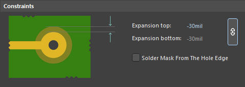
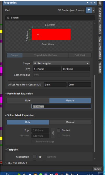
System requirements: Windows 2000,XP,Vista, Win 7 32/64 bit, Win 8 32/64 bit There are a handful of surface mount components on the top side of our example board so in the image above you’ll notice the gray coloring for solder paste on the pads for those components.Sprint-Layout 6.0 - Design your own Printed Circuit Boards Solder paste files are necessary for the top and bottom side of your design when using surface mount components on those layers. When the board is populated with surface mount components, solder paste helps the solder flow better as it bonds the component pin to the copper on your PCB. The pads on the surface mount components you use in your design will specify solder paste within the exposed copper region (not covered by solder mask). Solder paste is a material used to assist in the soldering of surface mount components on a PCB. Of course, we can’t have solder mask covering where our components need to make electrical contact with the board! The only purple spots on the top layer are for component pads. This is apparent when examining the example solder mask image above. In other words, areas that aren’t to be covered, will be filled in on your solder mask layer. One final detail, solder masks are specified as negatives. If you do go with a solder mask, you must provide files for all layers where this covering is desired (top and bottom are the only options). Not every board includes a a solder mask and there may be circumstances WHERE you want a solder mask on the top layer, but not the bottom or vice versa (at high speeds there are some performance issues to consider with solder mask). This thin green protective covering on the top and bottom of a PCB is called the solder mask and it helps protect traces from shorting when debris is present on your PCB. If you’ve ever seen a PCB you are no doubt familiar with their oddly green coloring.


 0 kommentar(er)
